Re-Conditioning Risc PC Power Supplies
Article by Paul Vigay
I should point out from the beginning that this article assumes that you have a relative competancy with a soldering iron and are aware of the dangers of taking power supplies apart. The power supply inside your computer contains high voltages and can be a dangerous place to go poking about.
Do not attempt the things mentioned in this article if you don't feel competent enough.
The most common fault
The most likely fault to occur to power supplies is the Schottky Barrier Rectifier to blow. This effectively means no voltage is coming out of the PSU, so the computer will not turn on, or the power LEDs on the front will briefly illuminate for about half a second and then go out. They'll be no fan activity.
What you need
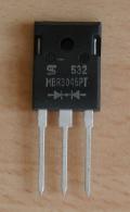 The Schottky Barrier Rectifier is part no. MBR2045CT and should be available from Maplin Electronics or an alternative electronic component supplier. The number on the device corresponds to the max.average current and the max.recurrent peak reverse voltage; 20A and 45V in this case. Unfortunately, this device might not be available, but I've found that Maplin part MBR3045PT (order code N18CC) is a good replacement (see right).
You will also require a Philips screwdriver, a pair of tweezers, a pair of wire snippers and a soldering iron. A multi-meter is also useful.
Remove the Power Supply
Unplug the computer from the mains and remove the power supply from the computer. This will require carefully removing the various slices and unscrewing a single screw at the front of the PSU, near the on/off switch.
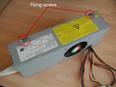
The power supply, removed from the computer
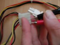
At this point you may want to test the resistance between the red and black leads on the PSU connectors to the hard drive or CD rom. There should be an approximate 20 ohm resistance. Less than this and it's highly likely that is IS the rectifier which has blown.
Measuring Resistance | 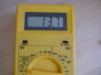
Checking Resistance |
Remove the two screws holding the cover on the power supply (highlighted above) and carefully fold down the side of the PSU. At this point you may wish to gently hoover the dust out, as it can collect quite a bit.
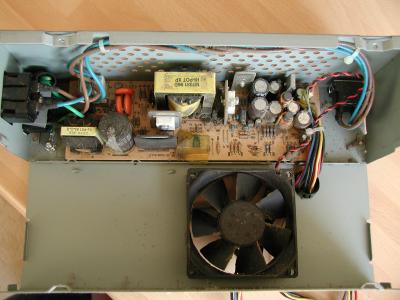
Inside the PSU
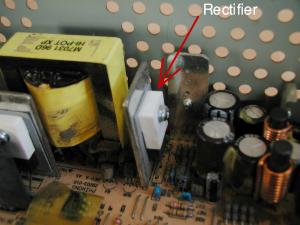 The rectifier in question is located just to the right of the transformer, shown in the close-up on the left.
Removing the old Rectifier
The old rectifier is held in place by a small bolt which goes through it and affixes it to a metal heatsink. You need to carefully remove the bolt, to free the rectifier from the heatsink and thin rubber sheaf.
Don't try de-soldering the component, as you can damage the fragile contacts on the PCB. Instead, use some fine wire-snippers to cut the three legs on the rectifier, thus removing it. You can then individually de-solder each leg and remove with the aid of tweezers.
Clean the holes to ensure that there is enough room to insert the replacement rectifier.
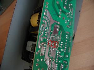
carefully desolder and remove the old legs. | 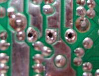
Clean the holes after removing the legs. |
Insert the legs of the new component into the holes, so that the writing on the rectifier is visible. Replace the screw that you removed, which holds it to the heatsink, ensuring that you don't tighten it too much, to crack the ceramic casing of the new rectifier. Fixing the screw back in place will also ensure that the legs are correctly positioned through the PCB and that you can re-solder the connections on the rear.
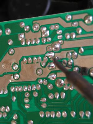 Make sure you've re-soldered the new legs and clean any solder or flux from around the PCB connections.
You can now carefully re-assemble the PCB and fix it back in the PSU housing. Make sure you re-insert the power leads through the small plastic clip in the side of the power supply casing.
Once re-assembled, you can test the unit by plugging back into the mains supply and switching on. If all is well, the fan should start spinning, indicating working power. If you get this far, it's highly likely you've fixed the fault and you can re-assemble the computer before finally powering it up.
The other fault which can occur is that the opto isolator fails. This is the six pin integrated circuit (IC) just in front of the transformer and I will describe the replacement of this in a further update soon.
I will periodically update this page when/if I find any more useful information regarding power supply issues.
Add a comment to this article
If you wish to add a comment to this article, please use the form below. Please note that by submitting comments using this form you are allowing all of the information submitted to be visible on this website. Your comment will be published immediately, so please proof-read before you add. Any comments deemed to be abusive or irrelevant to the topic of the article may be removed without warning.